432 MHz EME Antenna
G4RGK

The antenna is entirely home made,
the yagis are built to a design by DJ9BV (Dubus 2/91) and are 7.7 wavelengths
long. They are fed with open wire lines 3/16 diameter that are spaced ½” apart
using Teflon spacers. Each yagi has a folded dipole driven element with a feed
impedance of around 200 ohms. The two bays of four yagis are, in this picture,
fed with coax using a ¼ wavelength 4 to 1 sleeve balun. The parts for each
balun are machined in a lathe to achieve the correct transformation ratio. This
is an alternative arrangement to that normally used. It is less efficient
because it uses two baluns, two lengths of co-ax and a two way ¼ wavelength
power splitter. The preferred method of feeding is detailed below. It uses a
horizon line section which provides 100 ohms at the feed point, which is
transformed to 50 ohms by the ratio of inner to outer in the ¼ wavelength
balun.
Open Wire feed Lines.
The advantage that open wire lines have over Coaxial cable feeds is twofold. Firstly the feeds provide better receive performance due to the lower losses between the antenna and the Pre-amp. Secondly, they are unlikely to suffer from the ingress of water or condensation in the same way that coax does in damp climates.
From a mechanical point of view, the lines need to be engineered in such a way as to remain rigid in use with no interaction with nearby metalwork or deformation which will cause a change in impedance. The basic formula for calculation of the characteristic impedance of the lines is as follows.
Zo = 276 x log(2D/d)
Where D = the pitch spacing of the wires
And d = diameter of wires
Therefore to achieve a 200 ohm nominal impedance using .187” (4.76mm) diameter wires the pitch spacing would be .496” (12.6mm). The lines are spaced using accurately machined PTFE spacers, these control the characteristic impedance of the lines so the pitch must be accurate.
A practical implementation of the design is shown below.

The folded dipole is attached to the lines by M2 x 12 Stainless capscrews, The lines are made from solid 3/16 dia Aluminium Rod, the ends are tapped M2 to accept the screws.

This shows the 2 to 1 Balun in position feeding the horizon line section between the two bays of 4 yagis.

Here the co-ax lines between the two groups of 4 have been replaced with open wire lines. The length of the vertical and horizon lines in the bay of 4 are calculated to provide 200 ohms at the centre, therefore each section is 1674 mm long. The matching section between the two groups of 4 yagis is 4,720mm long and arranged so that there are no sharp bends and that it is clear of all metal obstructions.
The Balun

This picture shows the 1/4 wl Balun,The design was published by DJ9BV in Dubus magazine in 1992. It is fabricated from Brass and PTFE. The parts are silver soldered together and then Silver plated. It is designed to provide a 100/50 ohm transformation as well a Balanced to unbalanced transition.
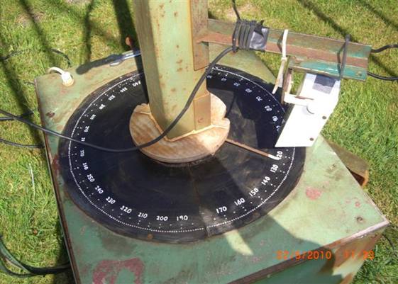
The
KISS azimuth indicator consists of a 360 degree protractor which is fixed to
the base, the rotating mast holds the pointer with the Camera above it which
also rotates with the mast.

I’m
not much of a photographer; this is the operator’s view of the Azimuth readout.
I prefer the analogue display to a digital one because I can see the outside Wx
conditions, it is particularly useful when it is windy.